


Hover to zoom
1 / 2 · Click to enlarge
At a glance
This product is a good fit for DIY builders and repair work.
Ideal For
- Repairs around the home
- Electronics bench work
- Workshop jobs
Buying Tip
Compare the pin layout and operating voltage with your circuit, and order a spare or two: small parts are easy to damage while soldering.
Specifications
| S.N. | Name |
|---|---|
| 1 | 103 capacitor※0805 |
| 2 | 20P 0805※ |
| 3 | 10uf/16V※ |
| 4 | 100uf/16V※ |
| 5 | 220uf/16V※ |
| 6 | The resistance value of the resistor is between 1K-3K ohms※ |
| 7 | The resistance value of the resistor is between 0-100 ohms※ |
| 8 | The resistance value of the resistor is between 8.5K-20K ohms※ |
| 9 | 10K exclusion※ |
| 10 | IN4007 diode※ |
| 11 | LED light※ |
| 12 | 78M05※ |
| 13 | Touch the button※ |
| 14 | 8M crystal oscillator※ |
| 15 | 74HC573※ |
| 16 | 74HC164※ |
| 17 | STC89C52※ |
| 18 | Single row of needles |
| 19 | PCB board |
Overview
The DC 9V SMT Soldering Test Kit Electronic Practice Set is listed in our range and suits DIY builders and repair work. The notes below explain the main specifications and what to check before you order.
Specifications explained
- S.N.: Name
- 1: 103 capacitor※0805
- 2: 20P 0805※
- 3: 10uf/16V※
- 4: 100uf/16V※
- 5: 220uf/16V※
- 6: The resistance value of the resistor is between 1K-3K ohms※
- 7: The resistance value of the resistor is between 0-100 ohms※
Before you order
Compare the specifications with your project or device, and check delivery times and return terms for your country in our help centre. Questions about this item? Email [email protected] with the product code.
Description:
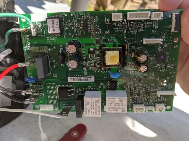
1. J1 and J2 are the power supply input terminals of the entire SMT board. It can work normally when connected to AC6V or DC9V. When working normally, all LED lights in this kit can work normally. At first, each group of LEDs flashes with water, and then flashes at intervals, and finally all Light up all the LEDs, then flash again, and cycle like this to check whether the LEDs are working and whether they are soldered well. If it is found that the corresponding LED does not flicker, it means that there is a welding error or a false welding.
2. The AC6V power supply is rectified by D1-D4 diodes, and then through each filter capacitor to pin 1 of the voltage regulator chip 78M05 (LED97 is always on, the rectifier circuit is working normally), and the output of DC5V is supplied to the whole test circuit through pin 3.
3. This test circuit is controlled by a single-chip microcomputer to work with 12 groups of 8-bit LED lights. Each group is composed of 1 74HC573 and 74HC164. One group can control 8 LEDs, 12 groups in total. Figure 1 is the control schematic diagram of one group. When working normally, all LED lights are on and can flash.
Specifications:
Product Name: SMD Soldering Test Kit
PCB material: FR-4PCB board
PCB size: 145*100MM
patch tape connection test
Power supply mode: DC DC9V
Applicable objects: junior welding patch personnel
Component Description: Common patch components are used
<
Package Include:
1× SMT Soldering Test Kit
(Note: The products shipped are loose parts, and the actual products need to be assembled by the buyer.)


Product Safety Information
Product Safety Information
Manufacturer
Shenzhen Yuner Yipu Trading Co., Ltd
Address
East 1087, Building 4, SEG Science and Technology Park, No. 3012 Huaqiang North Road, Huaqiang North Street, Futian District, Shenzhen, Guangdong, CN
European agent
VISHTEC ltd
Email
Address
3 rd floor office 5, Plovdiv 2 Liuben Karavelov bul, 4002 Bulgaria
UK agent
CET Product Service Ltd.
Email
Address
Beacon House Stokenchurch Business Park, Ibstone Rd, Stokenchurch, High Wycombe, Buckinghamshire, UK
Quick specs
- S.N.
- Name
- 1
- 103 capacitor※0805
- 2
- 20P 0805※
- 3
- 10uf/16V※
- 4
- 100uf/16V※
- 5
- 220uf/16V※