
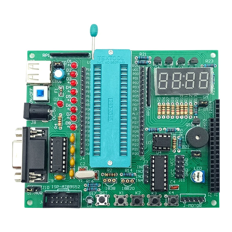
DIY JZ-K3 C51 Microcontroller Development Kit MAX232 USB DC Port Self-Reset Protection Multi-Interface Support LED Display Module
5.01 ratingThe DIY JZ-K3 C51 Microcontroller Development Kit MAX232 USB DC Port Self-Reset Protection Multi-Interface Support LED Display Module is a mid-range product designed for DIY enthusiasts and makers.
Available Offers
Free Delivery on this order. No minimum order value.
15-Day Easy Returns — hassle-free return & full refund.
Secure Payment — 100% safe checkout with UPI, Cards & Net Banking.
Available Offers
5% Cashback
Pay with UPI & get 5% cashback (up to ₹50) via Razorpay
No-Cost EMI
Available on select bank cards at checkout. 0% interest for 3 months.
Free Shipping
Free delivery on all orders. No minimum order value.
Cash on Delivery
COD available on orders up to ₹5,000 across India.
Ideal For
About This Product
The DIY JZ-K3 C51 Microcontroller Development Kit MAX232 USB DC Port Self-Reset Protection Multi-Interface Support LED Display Module is a mid-range designed for DIY enthusiasts and makers. It delivers reliable performance at an accessible price.
Why Buy from Elecvora?
Elecvora sources this product directly, cutting out multiple middlemen. Every order includes free shipping, a 15-day return policy, and secure payment via Razorpay.
Note: This is a DIY kit, you need to assemble and solder.
- Communication IC: MAX232
- USB to Serial Port for downloading and communication
- DC Port: 5.5*2.1mm, connects to a 5V power adapter
- Self-reset protection: for short circuit or microcontroller malfunction
- Components: LED flow lights, 4-digit common anode display, buzzer, stepper motor driver chip - ULN2003, memory chip - 24C02
- Sensors: 18B20 temperature sensor, infrared receiver interface
- Connectors: PO pull-down resistor, single-chip IO output pin, 5V/GND output pin, LCD1602 interface, LCD12864 interface, ISP download interface
- Three removable IC seats for easy replacement
Features:
1. Versatile Connectivity
Equipped with USB and DC power ports, the board offers flexible power and communication options, making it adaptable to various development environments and scenarios.
2. Enhanced Protection
The integrated self-reset protection ensures the board automatically shuts down in case of a short circuit or microcontroller malfunction, safeguarding your system's integrity and components.
3. Multi-functional Interface
This development board supports multiple interfaces including LCD1602 and LCD12864, offering a wide range of display capabilities and allowing extensive testing and prototyping possibilities.
4. Comprehensive Component Suite
Featuring elements like LED flow lights, buzzer, stepper motor driver chip, and standalone buttons, it provides essential tools for a diverse array of electronic projects and hardware experimentation.
5. Easy Component Replacement
With three removable IC seats, this board allows for straightforward swapping of components, facilitating quick upgrades and customization without the need for complex soldering processes.
Package Included:
1 x DIY JZ-K3 C51 Microcontroller Development Kit


